The Rugged MEGA

Quick Look
The Rugged MEGA is directly compatible with the Arduino Mega, MEGA2560 and other compatible boards. It uses the same microcontroller (ATmega2560), same Arduino GUI, same clock frequency, same connectors and connector positions which also makes it compatible with shields designed for Arduino Megas. However a quick look at the Rugged MEGA board will show the differences between a standard Mega and the Rugged MEGA. A large array of protection on Analog Pins 0-15, Digital Pins 0-21, low capacitance TVS diodes, built-in DIN rail mounts and more.
So what do all of these added components do and how do they affect performance and keep your board protected? The chart below offers a Quick Comparison between a standard Arduino Mega and the Rugged MEGA. The MEGA offers a substantial increased performance and protection. Ideal for industrial applications, robotics, 3-D Printing, and demanding applications. Note potential failure points listed in RED.

The Rugged MEGA can be purchased on the MEGA Product Page.
Drivers / Installation
The Rugged MEGA uses the FTDI FT231X. Drivers can be found directly on the FTDI website.
The MEGA will show up in the device manager as "USB to Serial Converter". It will automatically pick up the FTDI drivers from the normal windows driver finder, but will show up as USB to Serial Converter.
An optional driver file is available by clicking this link: MEGA Driver File. This driver is the standard FTDI driver, but has been modified so the the descriptor is Rugged Circuits Ruggeduino MEGA. This in return will make the MEGA show up in the device manager with said name. Either file will function perfectly with the Arduino environment.
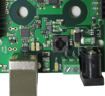
Power In
The MEGA is powered from one of three sources:
USB port: 5V is provided directly from the USB port. A 500mA PTC (resettable fuse) protects the computer from overcurrent.
DC power jack: a 2.1mm center-positive DC power adapter can supply 3.5V - 30V. This power input is also protected by a 500mA PTC.
Vin: this connector pin can either source power to the MEGA (3.5V-30V) or draw power from the DC power jack. Please note that V- is Ground and V+ is Voltage In.
When more than one power source is present, the automatic power switching circuit selects external power (DC power jack or Vin, whichever is higher) when available, otherwise USB power is used. This behavior is the same as the Arduino Mega.
Power Out
The Rugged MEGA utilizes a 5V switching regulator for efficiency and a 3.3V linear regulator for noise suppression. The Rugged MEGA can supply power to shields or external circuits in three ways:
+5V output: the +5V connector pin is the same voltage seen by the microcontroller. The current from this output is naturally limited by thermal protection on the on-board 5V regulator when externally powered, or limited to 500mA by a resettable fuse when USB-powered.
This +5V output can typically source 700mA when the DC power jack voltage (Vext) is 12V or higher, and less current as Vext decreases -- it can even source 150mA at +5V when the Vext voltage is as low as +3.5V!
On the MEGA, the +5V output is protected against applied high voltage. If, for example, you apply 30V to this pin by mistake, the MEGA will not be damaged. If you do the same thing on an Arduino Mega, you will destroy it!
+3.3V output: the +3.3V connector pin sources 300mA (Vext is 12V or higher) and will start to limit the current between 400-600mA. Note that this is quite a bit more than the limit of the Arduino Mega. Like the +5V output, as Vext drops so does the current sourcing capability. Current used on the 3.3V rail is directly subtracted from the 700mA limit on the 5V rail. For example, if you draw 200mA from the 3.3V rail, 500mA is left available on the 5V rail.
As with the +5V output, the +3.3V output is protected against applied high voltage; if you apply 30V to this pin by mistake, the Rugged MEGA will not be damaged.
Vin: the Vin connector pin can draw power from the DC power jack. This power input is limited to 500mA by a PTC (resettable) fuse. The 500mA PTC fuse protects this input against conditions like short circuits to GND (which would damage an Arduino Mega).
Programming
The MEGA is programmed in exactly the same way as the Arduino Mega; the full details can be found in the Programming section of the Arduino Mega product page. Any programming language that supports a compiler that can output a binary suitable for the atmega2560 can be used. There are MANY different programming languages, but here's a list of some others that some have used successfully:
https://www.makeuseof.com/tag/programming-languages-can-use-arduino/
In summary:
From the Arduino GUI, select “Arduino Mega” from the Tools->Board menu.
The Optiboot bootloader is preloaded on the MEGA so it is ready for uploading sketches.
The ATmega2560 can be programmed through the bootloader or through its ICSP header.
Jumper J9- AREF Options/External Reference
By default, the AREF pin is connected to a 5V shunt reference (LM4040). If a different reference is desired, J9 (the jumper next to the the SDA pin) needs to be cut.
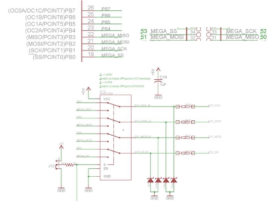
Jumper J12
The jumper position allows the MEGA to use the SPI peripheral on shields designed for the Mega or the UNO/Ruggeduino.

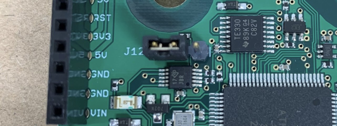
Position 1- J12 is in the 'normal' position (equivalent to Arduino Mega 2560) when a jumper is placed across the two pins closest to the female headers on that side of the PCB. This connects pins PB4-PB7 to D10-D13 and leaves the Mega's SPI port (PB0-PB4) connected to pins 50-53 as on a normal Arudino Mega 2560. In this configuration the Rugged MEGA mimics the Arduino Mega and allows use with shields designed for the Mega. If you are converting directly from a regular Arduino Mega or equivalent, and you want to maintain the identical behavior and wiring, then Position 1 is what you will need.
Position 2- When the jumper is switched to the other position (towards the 16 lead IC), D10-D13 are connected to PB0-PB3 instead of PB4-PB7. This allows the native SPI port on the Rugged MEGA to control or use shields that were designed for the Uno that use SPI communications on the D10-D13 lines. One side effect of this mode is that pins 50-52 are essentially connected to pins D10-D13, so D10-D13 and Pins 50-52 cannot be used simultaneously with different signals - as both of them are shared on PB0-PB3. Note that pins A4-A5 are also affected. If you want to utilize shields for the Uno/Ruggeduino platform on the Rugged MEGA (not possible with an Arduino Mega), then you need Position 2.
Pins D10-D13
Pins D10-D13 are slightly special pins that have slightly different drive characteristics because of the ability to put the SPI pins in the traditional Arduino SPI placements. Pins D10-D13 may have a a reduced voltage compared to the other digital pins because the SSR inputs can draw significant current.
Rugged Protection
The Rugged MEGA and Rugged MEGA-ET offer the same great protective features as our Ruggeduino-SE and ET variants. Below is a graphic that denotes the protected pins which are labeled as "Protected Digital & PWM", "Protected Communication", and "Protected Analog".

Protection Details
The Rugged MEGA was designed to withstand common electrical mistakes, thus ensuring your Rugged MEGA will last a long time. This section describes the details of these protective circuits.
I/O Pin Protection
Every "protected" I/O pin has a 5.1V zener diode and 220 ohm 30mA PTC (resettable fuse). The equivalent circuit is shown in this figure.

This protection circuit means:
Every I/O pin can have up to 24V applied to it and will still not be damaged (only 10V for the Rugged MEGA-ET).
Every I/O pin can be short-circuited to ground and will still not be damaged
Every I/O pin can be short-circuited to another I/O pin and will still not be damaged
In addition, the 220 ohm PTC can take the place of series resistors in many applications, such as lighting LED’s, driving transistors, and so on. Here is an example of an Arduino driving a transistor through a series resistor, and how the Rugged MEGA or Ruggeduino simplifies the circuit due to its built-in 220 ohm series resistance.
24V/10V Max Input GPIO
The Rugged MEGA general purpose input pins will tolerate a maximum of 24V and the Rugged MEGA-ET 10V. While the inputs are 24V/10V tolerant and will read logic HIGH anywhere higher than ~2V, there is no signal division on the PCB that will allow the analog inputs to read an analog value higher than the 5V reference. An external voltage divider/buffer is necessary for signal division.
PROTECTED PIN Current Ratings-Rugged MEGA
The microcontroller pins are rated to source an ABSOLUTE maximum of 40mA, but really shouldn’t go over 20mA. The PTCs on the protected pins will hold up to approximately 14mA continuous, but will trip in the ~30mA range and start limiting current.
AREF/VREF
The Vref pin can NOT accept 24V. In order to read a 24V analog signal without maxing out the A/D converter at 5V, a divider will have to be employed. Depending on the impedance of the divider, a buffer may also be required in order for leakage in the zener diode to not artificially skew the value as you approach 5V on the pin.
VIN Pin
The VIN pin has overvoltage protection, overcurrent protection, and reverse voltage protection. The overvoltage protection will clamp any transients to <45VDC and starts to conduct at approximately 31V. The circuit employs a TVS which protects from momentary transients. If a steady state voltage is applied above 31V, damage will occur. The VIN pin is also protected up to 500mA with a resettable fuse.

Similarly, you can connect LED’s directly to Rugged MEGA or Ruggeduino digital outputs without any resistors and not worry about destroying them due to excessive current.

I/O Compatibility
The benefits associated with the protective circuits far outweigh any compatibility related issues. We have sold thousands of protected devices and compatibility is rarely an issue. While we can't physically test all Arduino compatible shields and accessories we can ensure you that compatibility is next to never an issue. If a shield works with an Arduino it should work with a Rugged Circuits device.
In some instances the protective components, the 220 ohm PTC and zener, can produce slightly different results compared unprotected circuits found on standard and clone Arduinos. This may come at an initial surprise to the user, but being educated on the reason, it can be easily addressed. Here is an example:
Application: Reading/Mapping analog input voltage with 68k and 12k voltage divider to measure 20 to 30VDC.
Results: With the Rugged Circuits microcontroller everything is linear and values are accurate up to 20V. Over 20V accuracy falls off and at 29V it reads 25 volts. The divider is only measured to 3.9VDC at 29V. The exact circuit works with a Chinese Mega.
Reason and Solution: The 220 ohm PTC and the zener are skewing the results. With a high impedance source (68k+12k voltage divider), the leakage in the zener increases exponentially as you get closer to 5.1V. Under ~3-4V, there should be very little leakage. As you increase from there, the zener starts leaking microamps of current and makes the circuit non linear. There are three methods to battle this - add an op amp buffer between the voltage divider and the analog pin, use a lower impedance voltage divider, or scale the input voltage to only use ~3V of the reference and lose a little resolution. The first method will fix the issue completely, the second one will help, and the third should all but eliminate the issue.
If you do have an application where this built-in 220 ohm resistance is not wanted, you can easily change it. Every I/O pin has through-hole pins surrounding its PTC fuse that can be jumpered with either a wire for 0 resistance or with a standard resistor. Here is a picture showing how to bypass the 220 ohm PTC for pin D. Note that on the Rugged MEGA ET, the 220-ohm PTC is replaced with a standard 220-ohm resistor. This enables operation down to temperatures of -40C but only provides per-I/O-pin overvoltage protection of 10V instead of 24V.

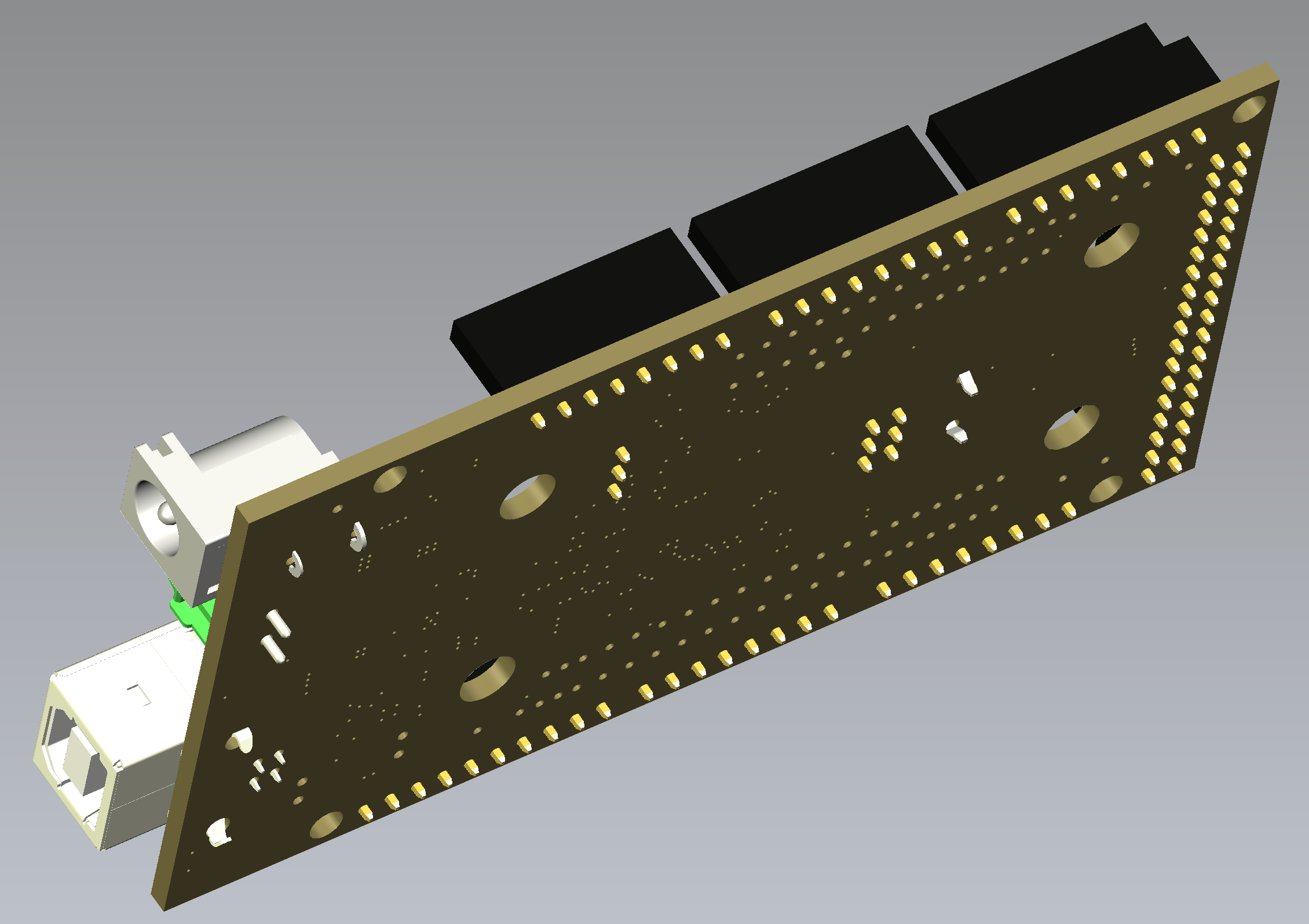
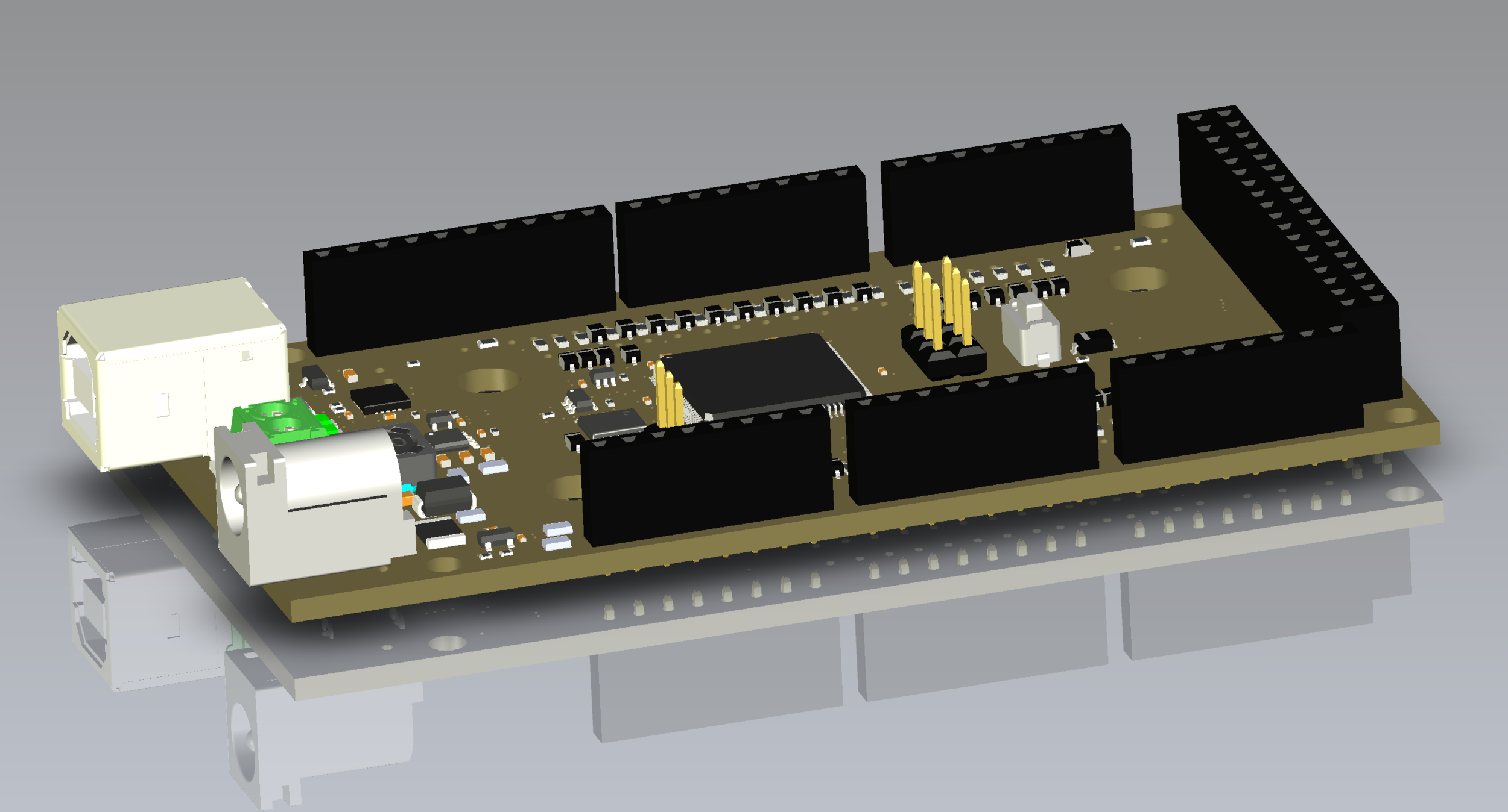
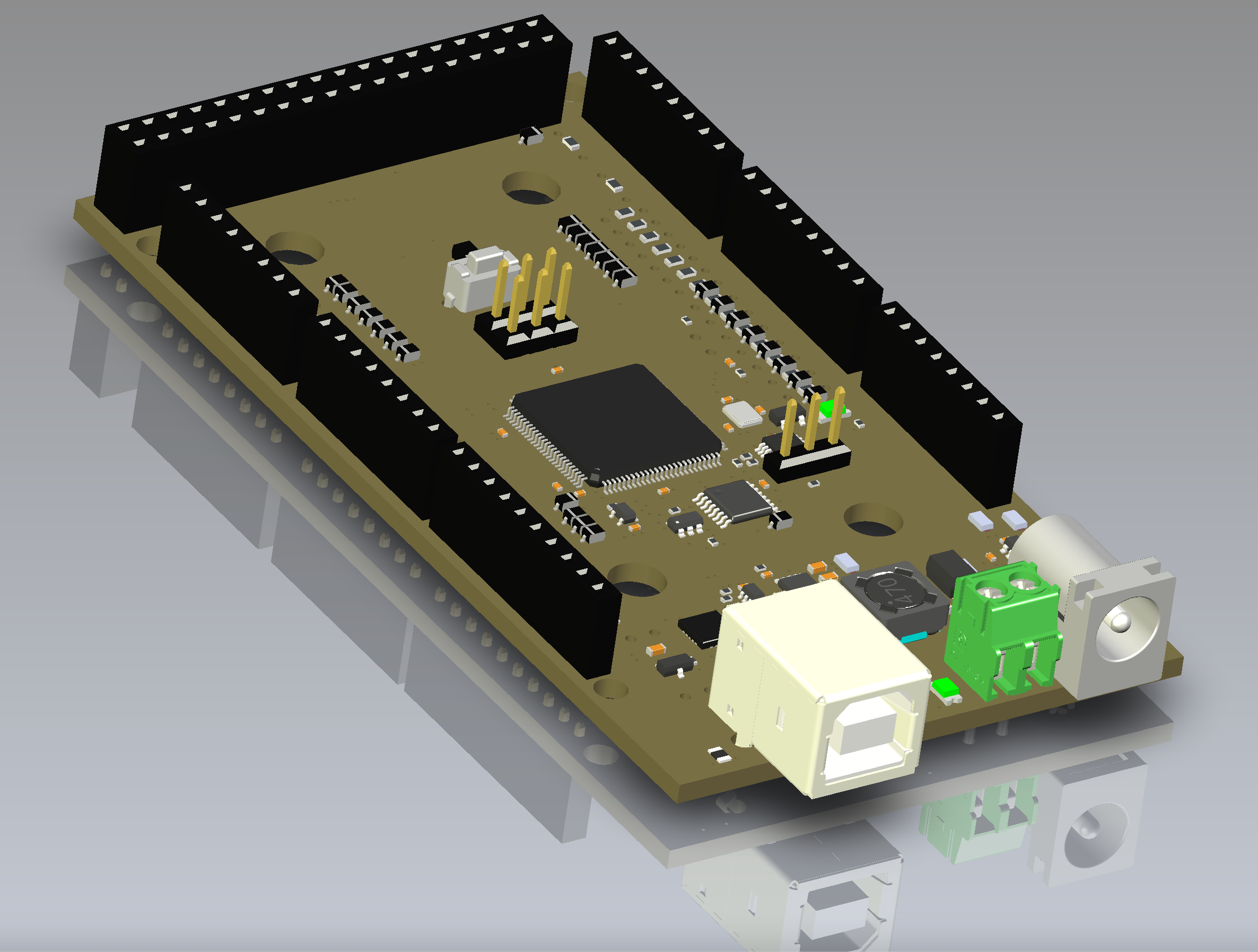
Drawings and 3-D Modeling Data